Tuesday, September 6, 2016
Labor Day
Yes, another long weekend filled with labor.
We made progress with yard maintenance by raking up about 1/2 the yard and hauling off four loads of yard debris to the burn pile. Unloading the piles from the trailer is almost more work than loading it but after a couple trips we came up with a solution. By laying a tarp on the bed of the trailer and loading everything on top of that, we could just pull the tarp out and everything comes out in one big pile. One of the secrets to making this work is to not fill up the trailer too much otherwise it’s too heavy and we’d need more muscle to pull it out. One more day of raking and hauling and we may be ready for winter.
Larry, Barbara, and Genny make the back yard/dog area look good again too. The sewer line was wrapped up to prevent roots from getting in and the trench and septic take covered up. No more trench in the back yard, Yay!
Upstairs, the custom cabinet work continues. One bank of drawers is almost ready for the actual drawers to be installed. Doing something like this for the first time is definitely a learning experience. We started with the premise that the drawers should be as wide as possible so I started building the carcasses so they’d just fit between the beams. But when we looked at adding the face frame trim, it became apparent that we needed the trim wide enough that the top tip out drawers were all proportional. It would look strange if the outside tip out drawers side frames were 4” wide but the middle one was 1”. This change meant that the carcass width needed to be about 6 to 7 inches more narrow. Turns out that building the face frame first and then building the carcasses to match would have probably saved 4+ days of effort. But nothing to do now but continue on with the oversized carcasses.
I think I’m down to about 2 hours per drawer carcass now that I don’t have to think too hard about what needs to be done. It’s just cutting fitting each custom piece of wood. It feels like I’ve been working on these for months and none of the actual drawers have even been built yet. Given that I have about 2 days of work into the first bank, I think I know what I’ll be doing next weekend….
Back bedroom
-
Dog cubby baseboard -
Dog cubby outside trim - Figure out knee wall design — getting close
-
Knee wall door trim -
Build/install bookcase -
Install hangers for clothes - Install drawer carcasses — a couple are set in place
- Install drawer boxes
- Install drawer trim
-
Install baseboard - Trim wall to ceiling corners
- Install conduit for ceiling fan — almost finished
- Build new ceiling fan mount
- Install new ceiling fan
Front bedroom
-
Paint balcony door - Frame knee walls
- Trim knee walls
- Door for closet
- Drawers and doors for knee walls
- Install baseboard
- Install wall to ceiling corner trim
- Install conduit for ceiling fan
- Build new ceiling fan mount
- Install new ceiling fan
- Install grill cover for vent fan
- Install window blind
Monday, August 22, 2016
The sting
Every now and again we need to step outside and do some yard work. This weekend, Genny pulled some weeds/plants from the driveway and we both raked up some leaves, stick, pine cones, and pine needles. Now that we’ve started, it’s more obvious how much more we need to do. I think Labor day will be yard labor day.
A couple of weeks back we noticed (well our guests noticed) a large wasp nest hanging off the shed overhang. Wasp spray was on the list, but we forgot it so the nest is still intact. I guess when I was banging around in the shed looking for a couple of pieces of wood, I woke them. When I left the shed and slammed the door, it must of irritated at least one wasp and it decided to sting me on the back of my arm. A good reminder that we really need to get some wasp spray. Larry, I think I have a job for you up at the cabin … just kidding.
So far, with the drawer boxes, I’ve been building them the same size for each side of the room. We’ll, that’s about to change. The knee walls aren’t identical between the two sides and while the difference isn’t great, it’s enough to cause the top drawers to differ in height by about 1 inch.
A bunch of time was spent measuring the drawer box placement. Since the boxes are built at home then brought on-site to assemble and place, getting good measurements is critical.
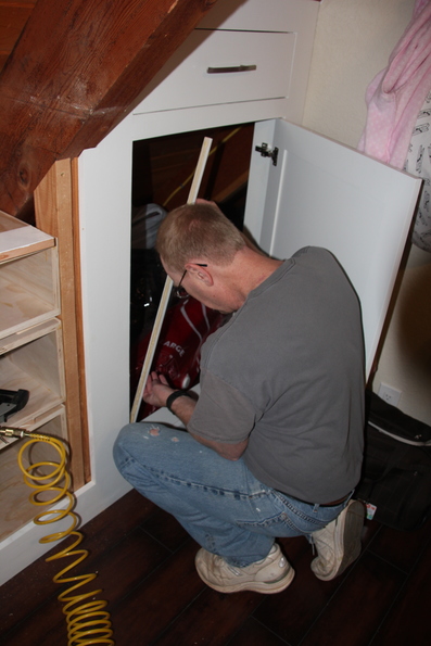
This weekend we made the side trim pieces for the center drawer stacks. Again, they are slightly different from side to side. Once we had the trim pieces fitted, we started looking at how the drawer boxes align and what additional work is needed before we can mount the drawer slides. While thinking about this we realized that the tip out drawer above the drawer stack was going to be a problem. For the cubby and storage areas we can get behind the tip out drawer and we needed to do that to reach the hinge screws. With drawers in place, there’s no way to get behind the tip out drawer (and thus, no way to install the hinges). The only solution seems to be to build the drawer trim as a face frame, build and install the tip out drawer in the face frame trim and then, once it’s all built, attach it to the knee wall. At least we figured this out before attaching the trim!
We installed the door stops for the storage area knee wall doors. It’s just a small thing, but now with the doors aligned properly when closed, it just looks so much better.
Back bedroom
-
Dog cubby baseboard -
Dog cubby outside trim - Figure out knee wall design — getting close
-
Knee wall door trim -
Build/install bookcase -
Install hangers for clothes - Install drawer carcasses — a couple are set in place
- Install drawer boxes
- Install drawer trim
-
Install baseboard - Trim wall to ceiling corners
- Install conduit for ceiling fan — almost finished
- Build new ceiling fan mount
- Install new ceiling fan
Front bedroom
-
Paint balcony door - Frame knee walls
- Trim knee walls
- Door for closet
- Drawers and doors for knee walls
- Install baseboard
- Install wall to ceiling corner trim
- Install conduit for ceiling fan
- Build new ceiling fan mount
- Install new ceiling fan
- Install grill cover for vent fan
- Install window blind
Tuesday, August 2, 2016
What to do when staying at the Scary Cabin (part 1)
It’s been just over three years since we bought this cabin in the woods and we’ve been working pretty much non-stop remodeling it. Seems like it’s about time for a break. So we decided to take some time off from work and from cabin work and explore the area a bit.
Day 1.
We had previously taken a drive to Quincy and passed through Grey Eagle and the Basin Lakes area on the way back. It looked like there were some nice hiking trails out that way so that was our first stop. After doing some research it looked like there was a nice hiking trail called the Bear Lake Loop so we made that our destination. Suspecting that this area could get quite crowded on a weekend, we opted for a Friday instead. It’s about a 2 hour drive from the cabin to the Basin Lakes area. To our surprise, the parking area for this trail was packed with some cars lining the narrow road leading up to it. We managed to find a wide area just down the road a bit. We started on the trail heading towards Big Bear Lake. The trail is well defined with nice views and at this point you’re headed a bit up-hill. When we got to Big Bear Lake, we detoured to get to the shore and worked our way around the lake to a somewhat secluded spot. There we let Sandie swim a bit and Duke got his feet wet.
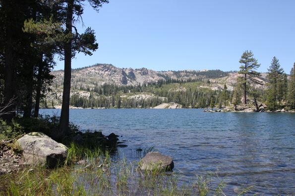
After our rest stop, we continued on the trail to Little Bear lake. Little Bear lake is quite small compared to Big Bear lake. We didn’t stop, but continued up the trail to Cub lake. Cub lake is very small.
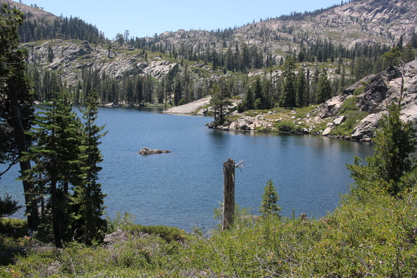
At that point we decided to try and make it to Long lake but Sandie’s feet started to get messed up by the hot rocks on the trail and instead, we headed back.
We also checked out a couple of other locations. There is a Fern Falls trail that leads to a water fall, it’s a short, paved trail, but we were told no water was flowing and we knew Sandie couldn’t handle the hot pavement so we’ll leave this one for another day.
Then we drove down to Salmon lake. The crowd there was much larger and parking was non-existent. This seems to be a popular lake for boating as there is a boat ramp. There’s also a lodge on the other side of the lake and the only way to get to it is to cross the lake in some kind of watercraft.
The trip there and back passes through a couple of stop worthy towns. Sierra City and Downyville. A lunch trip to Downyville would make a nice trip. There’s an old gold mine in Sierra City, the Kentucky mine. They do have tours so we’ll have to check that out at some point.
Day 2.
We planed to drive a couple of segments of the Backcountry Discrovery drive that the forest service put together. We started just outside of Laporte and headed towards Gibsonville on the old gravel/dirt roads. The guide does a good job of directing you and pointing out interesting historical sites. The road is fairly rough in places. Along the first section we did find a small steep spur that ended at the top of hill with great views. This would make a good stop for lunch if timed right. The first segment ends at Harrison Flat.
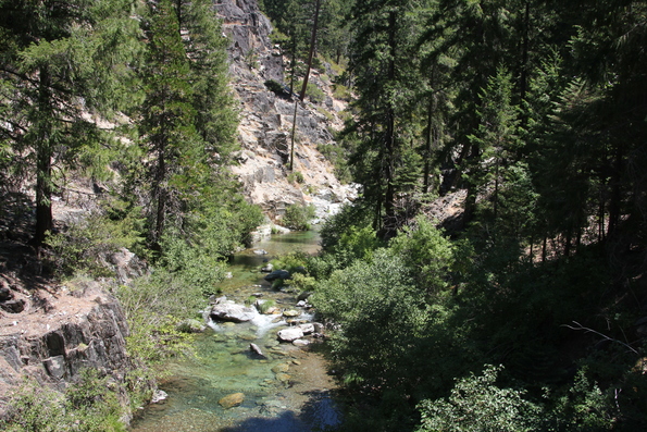
The second section is more of the same but with less historical sites. The second section ends at Hwy 70. We hadn’t planned on doing the third section but it did take us back toward home and the book said it was the easiest section of them (or something to that effect). Turns out they lied. The road was very rough and overgrown. We ended up with lots of pinstripping on the 4runner. I don’t think we’ll be doing that section again any time soon.
Day 3.
We had two goals for this day. Check out the Feather Falls trail and Big Bald Rock. The first stop was the Feather Falls trail. This trail is a bit more difficult than what we’re currently capable of so we only hiked in about a 1/2 mile. For that section at least, the tail is well maintained. Probably best to do this earlier in the year with cooler temps and more water for the falls. On the way back to the main road we turned off to investigate what looked like Lake Orville access. We did find an unmarked area that allowed us to drive almost to the water’s edge. This could be a good place to take the dogs swimming. After that, we stopped in Orville for lunch and to wash the dust of the 4runner. Then it was on to Big Bald Rock. The tailhead doesn’t look like anything special but then you encounter this:
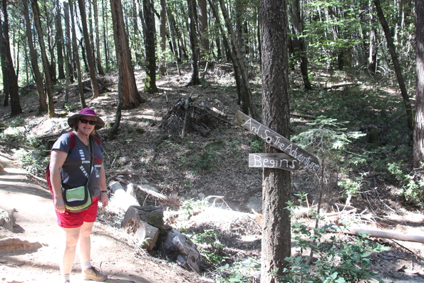
After a short walk (the tail is only about a 1/4 mile) you get to the main attraction. Rocks, lots of rocks.
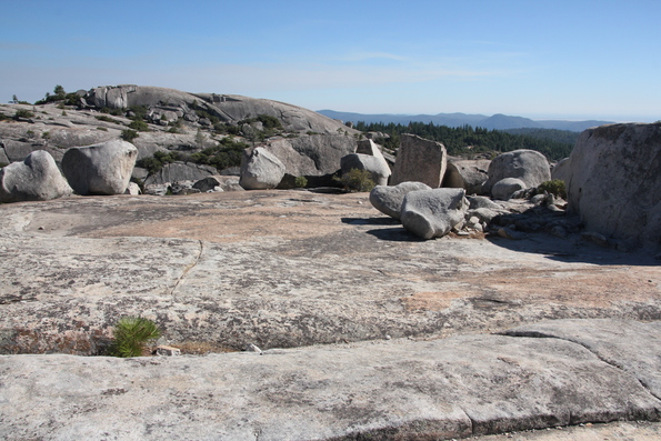
You can wander in and around the rocks for hours marveling at the strange shapes that mother nature has created. The only real downside is that there isn’t much shade so be prepared.
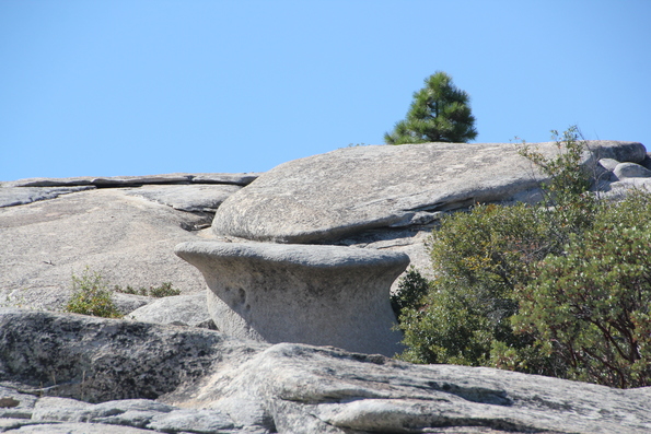
It was a lot of driving over 3 days, but now we have a better idea of what’s around and are excited by the prospect of more exploring.
Monday, July 25, 2016
Third time’s a charm…
The bookcase was mostly ready for final paint, it just needed the last little bit of filler sanded down and the round-over’s routed. With those tasks complete, Genny broke out the paint and finished it off. It turned out pretty nice.

The south side knee was next on the list. We finished up the tip out drawers on that side and installed the drawer pulls on all the tip out drawers. If you recall from a couple of post back, we had some trouble with the top rail above the outside drawer (the one on the left in the picture below). The first attempt at putting the rail in resulted in the nail to the finger. After that we made some measurements and took the piece home. This is kind of a tricky piece to cut. It’s a 45 degree rip cut with a taper. I didn’t think I had anything up at the cabin that could do that so using the table saw at home we made attempt #2. This one fit good but the taper wasn’t quite right and the drawer opening was more trapezoidal than rectangular. It really didn’t look right. So on to attempt #3. Using bubble gum and duct tape I managed to clamp a guide to the board and cut the 45 + taper using a hand circular saw. This one actually came out right with a nice rectangular opening.

The next task was to run the new electrical for the ceiling fan. The conduit and electrical box will end up being behind the bank of drawers so getting that in place before installing the drawers seemed like the right order. Since the existing ceiling fan and mount will be replaced, The final bit of conduit isn’t finished, but it gets the job done and as a bonus, removes the extension cord that was powering the fan. Note that the extension cord to the fan was not our solution.
We’re cutting the parts for the bank of drawers at home (again, bigger table saw makes cutting plywood sheets much easier) and bring them up for on-site assembly. We’ve also decided that it’s a lot easier to carry the individual parts up the stairs than completed boxes. Three boxes were built and set in place. These aren’t fixed in position yet but will serve the purpose of figuring out drawer slide mounting and trim size. You can see the results in the picture above.
Continued working on the knee walls over the weekend.
Back bedroom
-
Dog cubby baseboard -
Dog cubby outside trim - Figure out knee wall design — getting close
-
Knee wall door trim -
Build/install bookcase -
Install hangers for clothes - Install drawer carcasses — a couple are set in place
- Install drawer boxes
- Install drawer trim
-
Install baseboard - Trim wall to ceiling corners
- Install conduit for ceiling fan — almost finished
- Build new ceiling fan mount
- Install new ceiling fan
Front bedroom
-
Paint balcony door - Frame knee walls
- Trim knee walls
- Door for closet
- Drawers and doors for knee walls
- Install baseboard
- Install wall to ceiling corner trim
- Install conduit for ceiling fan
- Build new ceiling fan mount
- Install new ceiling fan
- Install grill cover for vent fan
- Install window blind
Friday, July 15, 2016
The Rally Computer
Back in the late 80’s and early 90’s the Sacramento TSD rally scene was quite active. There were multiple rally clubs and typically at least one rally a month (The Friday Night Rally Series) along with various weekend rallies. Some of the folks involved were also involved at the national SCCA level. They typically used a “rally computer” to accurately track their distance and compute how close they ran to the ‘perfect’ time.
One bright fall Saturday, my rally partner, Jim and I ran a tour type T&D rally from Sacramento to Reno. Official mileages were given for every RI so it was possible to do manual calculations without the need for odometer correction calculations. We decided to try this armed with only a 4-function calculator, a pen and a pad of paper. This kept Jim very busy for most of the day and he didn’t get to see much of the scenery. After it was over, me being a software engineer, thought, “It would be pretty simple to write a computer program to handle all the calculations”. And thus, The Rally Computer program was born. I had a Zenith Supersport laptop computer that I had won in a raffel and it wasn’t being used for anything else so that made a perfect test machine. This was an 8088 based machine with 640K of memory, a floppy disk drive (3.5”!), a B&W LCD display, and a very large battery pack.
I started by writing some routines to handle time manipulations. I needed routines that could subtract and add two time values, convert a time (HH:MM:SS) to number of seconds, and convert a number of seconds to a time value. Delving into the Microsoft C documentation, I found a routine, _dos_gettime (), that would read the current time from the operating system and return it in a time structure. The time structure held hours, minutes, seconds, and hundredths of seconds. Perfect! I wrote all of the time functions to use the time structure.
The first version of the program would prompt for the mileage at the end of the odometer check. It would compare the official mileage with the stock odometer reading and calculate the correction factor. It would then ask for the out time. For the rest of the leg, it would prompt for a speed and a stock odometer reading and calculate the perfect time to that point. It would also mark the time-of-day when the ‘’ key was pressed and compare that time with the perfect calculated time and display the difference as an early/late number of seconds. By entering this information for each speed change, we would know how far off we were at that point. This worked OK but we soon found out that it was definitely not perfect. If we made any errors, either in entry or by going off course, there was no way to correct them. After almost every rally we would find something that didn’t work quite right or if changed, would make it easier to use. After almost 2 years of adding features, making changes, and redesigning it is finally to the point were we felt it was competitive with commercial rally computers.
So far all I’ve talked about is the software. After a while it became apparent that reading and interpolating the stock odometer and then entering that into the computer was a major cause of errors. The next step was to add some hardware that could sense the number of wheel rotations and calculate the mileage. This would eliminate errors caused by miss-reading the odometer and by typo’s while entering it. It would also free up the navigator as trying to type all those numbers while bouncing around could be a trying experience. We investigated various methods of getting data into the computer. Making the computer count pulses would take too much of the processors time and we didn’t think it would be able to keep up. The Zenith doesn’t have any card slots so a simple I/O board was out of the question. We decided to build an intelligent electronic odometer and interface it to the computer with an RS-232 interface. The next step was to come up with a way to count wheel revolutions. I had a speedometer/odometer for my bike that used a magnet on the wheel and a reed switch to generate pulses. We decided to try and connect a $35 bicycle speedometer/odometer (CatEye) to the car. We mounted the reed switch on the top of the back brake caliper. There was a bolt holding a heat shield that worked perfectly. We then glued a magnet to the inside of the wheel and once it was aligned, spinning the wheel did cause it to pulse. We then ran the wire up to front seat and connected it to the display module. The CatEye is capable of working with a wheel diameter from 20 to 28 inches and my car tires were about 23 inches. It actually worked, we were able to read distance down to 1/100th of mile and speed, at least we could until we exceeded the units speed limitation. If we went over 60 MPH the unit would stop reading correctly. Of course, why would we ever want to go over 60 MPH on a rally? After more testing we determined that the problem was in the CatEye display unit and not in the switch sensor. It was time to build the odometer. We did some preliminary designs using an 87C51FB micro-controller, a couple of binary counters, and a display unit. Everything looked good but it would be expensive and complicated to build. I poured through the Zenith hardware reference manual looking for a simple way to do byte size I/O. The printer port looked promising. It had a 1 byte output port and 6 input bits. After experimenting with it I found I could transfer 8 bits out and 5 bits in. Maybe we could do something with this after all. I told Jim I would need a 20 bit binary counter with latchable outputs. He said, no problem, we can put that on a single EPLD chip. So he did. We have a 68 lead PLCC chip with a 20 bit counter, latched and multiplexed outputs. The counters clock is tied to the reed switch so that every pulse increments the count by one. By setting the latch line high and setting a 3 bit value to the bank we want, we can read all 20 bits, 4 bits at a time using simple I/O calls on the computer. We had our odometer.
At some point, the big Zenith laptop was replaced with a smaller, lighter 80386 based notebook which we used until the rallying scene mostly died out in the Sacramento region . We used this not only to run rallies, but to help with the creation of rallies. Since we could log everything, it was easy to pre-run a rally and log the perfect times for each instruction and leg.
Around 2002 I started to revive the software. As computers were getting more powerful, it seemed like it should be possible to eliminate the counter hardware and just count the pulses with the computer. I did some experiments using the parallel port interrupt line and a simple Linux kernel module around 2003 but never finished it into a working version.
In 2007 I acquired an Intel Poulsbo based tablet. This had a 800×480 display and could run Linux. I thought this might make a good rally computer. At the time, my wife and I were creating rally events for the local Miata club so I thought getting The Rally Computer working again might help with those. The two challenges were how to count the pulses and updating the code to work with the GUI based touchscreen. Since I wanted to do this in Linux, GTK+ / Glade make the most sense for the GUI. I created a layout and ported over some of the basic functionality. Since the tablet doesn’t have a parallel port, would a USB parallel port adapter work? What about a USB mouse button? I did some tests where I wired up the mouse button to the hall effect speedometer sensor and had mixed results. The pulse counting was a bit flaky. Life took over and I never did debug the problems.
Fast forward to 2016. Computers and cars have progressed quite a bit. Small hobbyist computer boards with multiple I/O’s, good displays, Wi-Fi, and Bluetooth are available cheap. For $40 or less you can get a Raspberry Pi that’s many times more powerful than the Zenith Super Sport of 1988. Cars all have various speed sensors that are used for traction control and ABS brakes. All it took was one trigger to start the thought process of what it would take to bring The Rally Computer into the 21st century.
It didn’t take long to finish up most of the software conversion to GTK+ but the real challenge is still getting accurate distance data. A RPI has multiple GPIO pins and those could be used to implement a pulse counter in a Linux kernel module without too much effort. The source for the pulses could be one of the car’s VSS sensor leads but that would involve cutting and tapping a wire the ECU. A less invasive approach would be to go back to the original reed switch and epoxied magnets. Both of these solution will only work with the specific car that has the modifications. Is it possible to access the VSS signal from the OBD2 connector that’s been mandated since 1996? Time to experiment. ELM327 based OBD2 dongles are dirt cheap, like less than $10. There are numerous examples of connecting one to a RPI via Bluetooth or USB on the web. The ELM327 datasheet is available and describes how to communicate with it in great detail. Sounds like a plan.
With a bit coding to create an test application that connects to the ELM327 and pulls various sensor data, we’re ready to experiment. It looks like the VSS signal is not available, at least not through the standard PID’s. But the vehicle speed (in kph) is available. Tracking the vehicle speed over a very short period of time can provide distance data. But is the speed data accurate enough and can the ECU be queried quick enough to make this a practical plug-n-play solution? The test application has been able to pull speed data at approximately once every .6 seconds. The speed data is in integer kph and ranges between 0 and 255kph (0 -159mph).
The next step will be hook up the GUI app to the ELM327 and run some real-world tests to see how it behaves when the vehicle is driven normally. To do this, the RPI will need some type of local display and input. There’s a nice 800×480 7” touch screen display available for $65 that seems perfect for the job.
If this works, it will be nice plug-n-play solution that should work with almost any vehicle 1996 or newer and it can all be powered from a USB port in the car. Total cost:
RPI model 3 - $40
7” display - $65
ELM327 - $10
Total = $115

